 Crab
Claw Rig experimentsCrab
Claw Rig experiments
Crab
Claw Rig experimentsCrab
Claw Rig experiments| Using info from from this page which details the research of C. A. Marchaj into the aerodynamics of the crabclaw rig, as a jumping off point, I made a simple crabclaw rig for Summer Breeze. |
 |
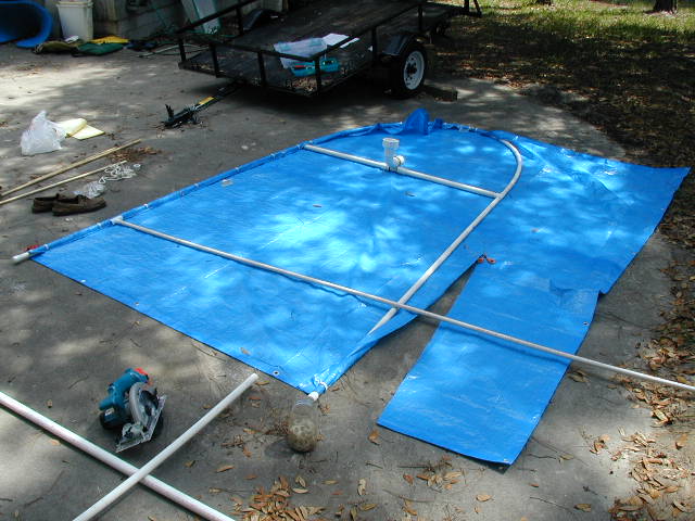
The above sketch is from the site just mentioned. I decided to see if this could be made simply of PVC pipe and poly tarp. I decided on 3/4" schedule 40 PVC for the frame. And 1" for the cross spar. My choice was based on it's ability to take the curve I was after. |  |
 |
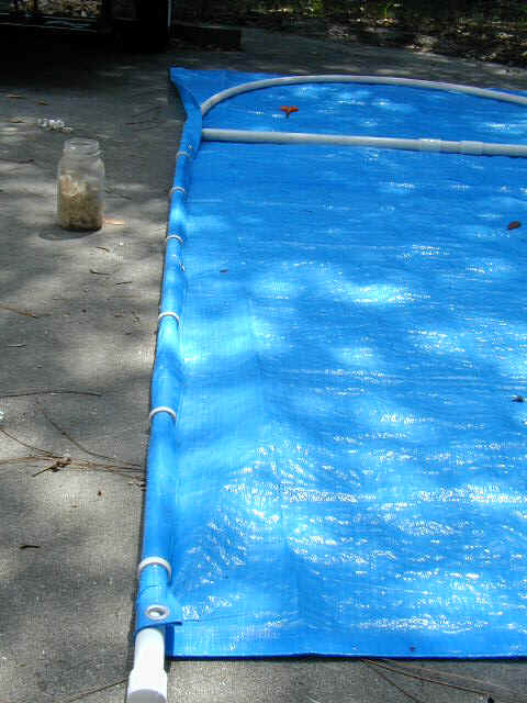
The upper hoop portion is 10' long. The cross spar is 5'. The "legs" are 7'4". The frame is laid on a poly tarp and attached with clips made from 3/8" slices of 3/4" PVC pipe. |
 |
Here's a clearer look at how the clips go on. I tried all kinds of different dimension to the "C" first, from a 1/4" to 1/2" thick, removing a quarter, a third to make the "mouth" and sanding the edges smooth etc. Ultimately, I ran a 2 foot length of pipe down my table saw, then sliced them on my bandsaw about 3/8" thick. |
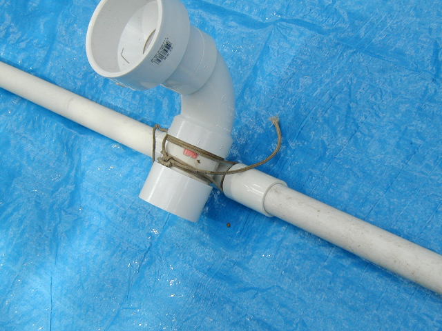 |
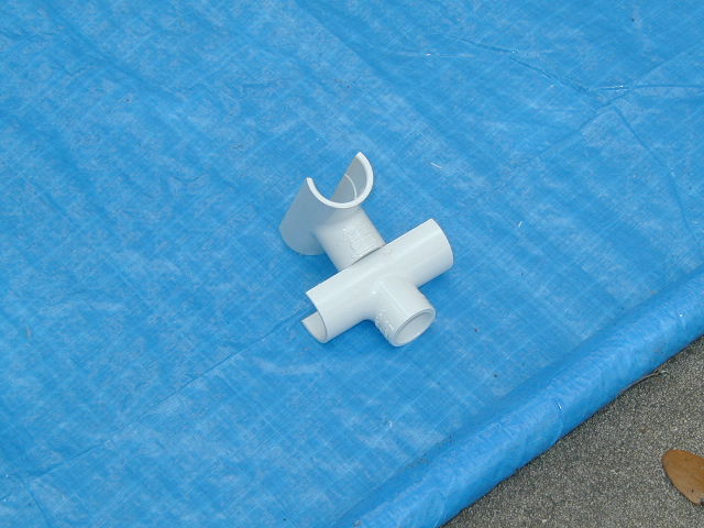
For this version of a crabclaw to work there needs to be some kind of "U joint." I did mine of line and PVC fittings. The sail can pivot for and aft and side to side, while the mast can rotate as well, though I'm not certain how necessary that is except for "weather cocking." |
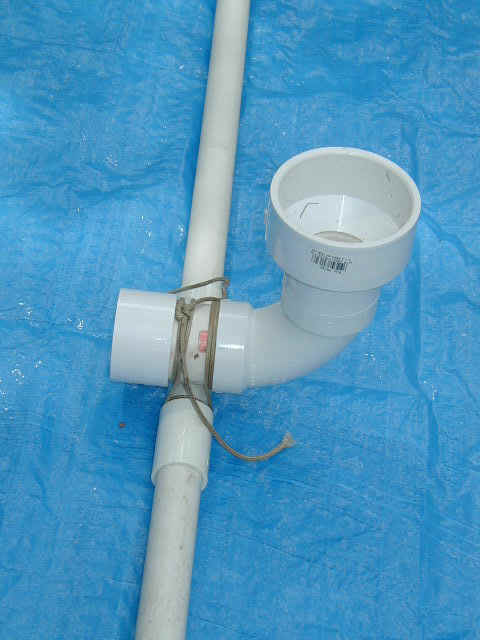 |
I used unions to keep the lashings in place on the spar. The sail can't slide side to side this way. |
 |
Here I'm making my way around the frame with the clips and also planing out the spreader position. The spreader is half inch PVC with ends cut to clip into the frame. |
 |
Here is a closer look at both ends of the spreader. |
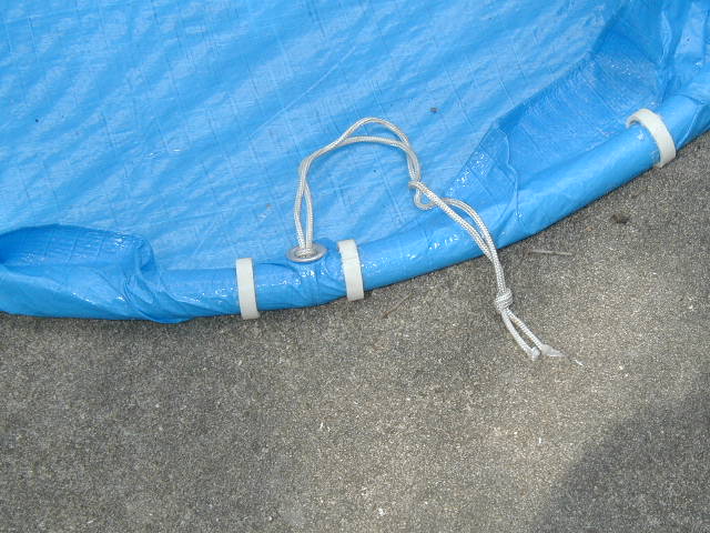 |
Before wrapping the polytarp around the head of the sail, I looped a length of line around the frame and through a grommet. |
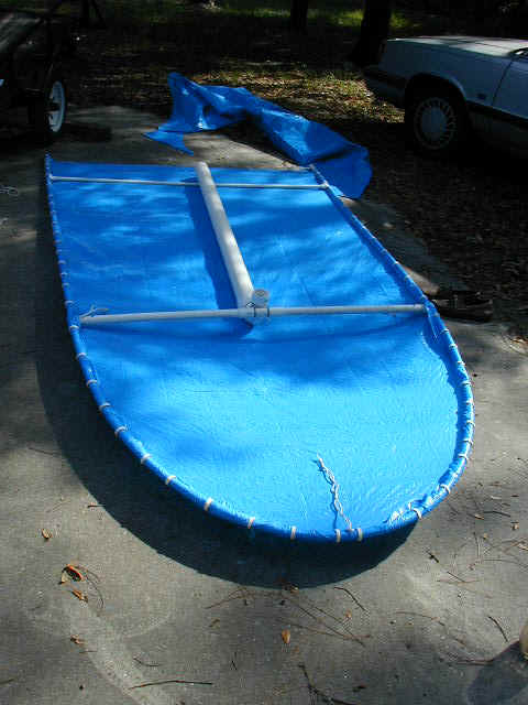 |
Here it is all clipped together. The 1" PVC cross spar has a 1" wooden dowel in it to stiffen it. Line loops are attached to the "Ts" at the end of the spar too to control tilt. |
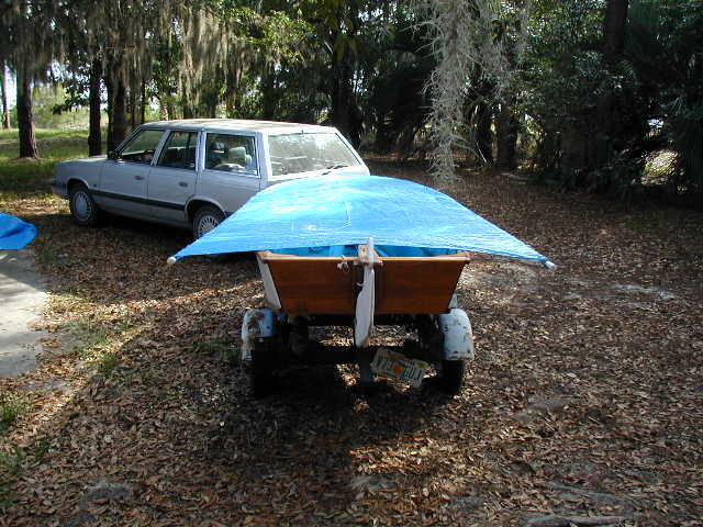 |
I set the whole gizmo on top of the boat and haul them down to the lake for fine tuning. |
 |
I immediately see that my first guess at 6' for the mast height is too tall. |
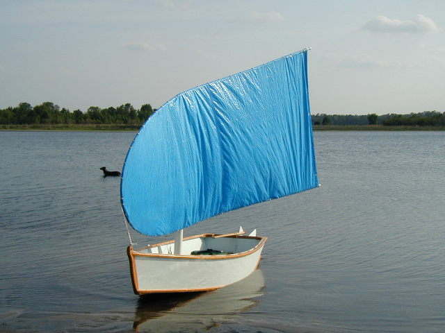 |
That's more like it. Still good head room, but not so high as to over power her in a gust. |
 |
Here you can see I've begun to rig the control lines. The bow line goes through the hole in the top of her cutwater stem. The tilt control lines are a continuous loop going through slots in her inwales. |
 |
Here's another close up of the universal joint. You'll notice I've not used PVC cement, but rather used small stainless steel screws to keep the joints together. This is partly because this is a prototype and partly in expectation that this might be dismantled and re-assembled elsewhere. |
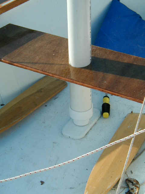 |
The 3" PVC passes through a hole cut with a hole saw in the mast partner, while a reducer brings it down to 2" PVC that fits in the mast step. |
 |
Her looks take a little getting used to. Still feels a bit like Mary Poppins on a bad day... ;-) |
 |
Here are two side views. The main sheet is also a loop attached to the aft corners with constrictor hitches. | 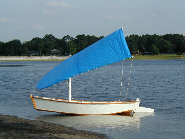 |
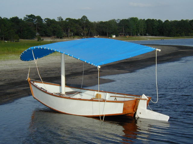 |
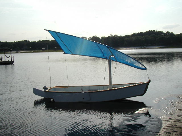
Here's a stern quarter view. You can see how this sail can function as a bimini when not actively sailing. That's partly what motivated her creation... a sunburn after glow from a weekend at Cedar Key. |
| My dog Mocha and I took
her on a trial cruise but, alas I have no pictures. It was pretty
educational. I was able to put her through all points of sail, even
pointing fairly well. The next step will be figuring out how to control
the lines. It's actually just three lines, the bow line, tilt line and
main sheet. However since the tilt and the main are continuous loops at
times I felt like I was doing macramé. Also the spars from the hoop back
are too flexible. I'll either have to stiffen them with some kind of
inserts or find another material.
It feels like there is a good bit of potential here. I designed, purchased materials and built this rig in about 3 hours. You can really feel a sense of lift in the rig at certain angles which is unusual and enjoyable. However, by contrast, the single control line on my sprit sail seems quite a feat of engineering. Stay tuned for further developments. May 7th. 2002- OK, this is day two of "further developments." I tried stiffening the frame by inserting some electrical conduit. Bad idea. Too heavy, made it want to fold up. But I did sail it again with my trusty faithful pup test pilot. The rig still shows amazing promise. Something that will take getting used to is that you can tilt the sail to windward like a windsurfer would, spilling excess wind without heeling. Both de-powering the sail and generating a bit of lift. An odd sensation in a traditional skiff. The bow line tilts the entire rig and also changes the center of effort. This means you can steer pretty well with sail controls alone, again like a wind surfer. I found some old light aluminum lateen spars while searching for stiffeners. Next step I think will be doing a more traditional triangular crab claw. I think I'll still clip on the polytarp with PVC clips. More later. On to the Next Page for more...
|
| This page created May 6th, 2002. Copyright David J. Beede 2002. |
Feel free to email me, David Beede simplicityboats
Back to Simplicity Boats Home Page